It is a precision instrument that can be used to measure internal and external distances extremely accurately. The vernier is a short scale which slides along a main scale, with its graduated edge in contact with the graduated edge of the main scale.
When measuring an object with scale, the length of the object is measured as 6.2 cm if an object measures between 6.1 – 6.2 cm. This implies that a small part of its length was neglected as we cannot record measurements less than 1 mm i.e., 1/10th of a centimetre, using metre scale. Hence a vernier caliper is used which can provide measurements less than 1/10th to 1/100th of a centimeter.

(Refer adjacent figure) 1 and 3 represents OUTSIDE JAWS – they are used to measure the external diameter or width of an object. Here 1 is a fixed jaw and 3 is a movable jaw. 2 and 5 represents INSIDE JAWS – they are used to measure the internal diameter of an object. Here 2 is a fixed jaw and 5 is a movable jaw. 6 represents the MAIN SCALE. It is graduated with value of one division on it equal to 1 mm. It is generally 15 cm to 20 cm long. 4 represents the VERNIER SCALE. It is a small movable scale which can slide along the main scale. It has 10 divisions marked on it, such that the total length of 10 divisions is equal to 9 mm. In other words, 10 vernier scale divisions coincide with nine main scale divisions. 7 represents the STEM of the vernier calipers. It slides back and forth along with the vernier scale. It is used to measure internal depth of cylinders or hollow tubes.

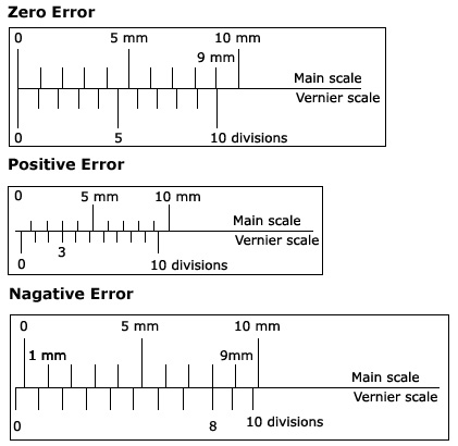
Errors are produced in an instrument due to its constant use. If the zero of the vernier exactly coincides with the zero of the main scale then there is no zero error (when the two jaws are in contact). There are two types of zero errors – negative error and positive error.
(i) Positive Error: When the two jaws are in contact and the zero of the vernier lies right to the zero of the main scale, the error is positive and the zero correction is negative.
(ii) Negative Error: When the two jaws are in contact and the zero of the vernier lies left to the zero of the main scale, then the error is negative and the zero correction is positive.

Screw gauge is an instrument used to measure small lengths, such as the thickness of a thin glass plate or the diameter of a wire or that of a small lead shot. In this instrument, the screw works through the inner surface of a hollow cylinder C. This hollow cylinder is attached rigidly to a U-shaped metallic framework F. On the hollow cylinder, parallel to its axis, is engraved a scale graduated in millimeters or half-millimeters. This is known as the pitch scale. To the head H of the screw is attached a sleeve S, whose edge is divided usually into 50 or 100 equal divisions. This is known as the head scale. In continuation of the screw is a shaft which ends in a perfectly plane surface B. A similar plane surface A is provided on the U-shaped framework exactly opposite to B. The two scales are so graduated that when the two plane surfaces are just in contact, the zero of the head scale coincides with the zero of the pitch scale.
Principle of Micrometer Screw Gauge:
The micrometer screw consists essentially of an accurately cut screw working inside a fixed, close-fittings nut. When the screw is given one complete rotation, the tip of the screw always moves through a distance P, known as the pitch of the screw (fig). In a micrometer screw, the pitch is usually 1 mm or 0.5 mm. A circular disc is fixed to the head of the screw. This circular disc is usually divided into 50, 100 or 200 equal parts, so that the screw can be rotated through any known fraction of a complete revolution.
If the pitch of a screw is 1mm and if the circular disc is divided into 100 equal parts, then on rotating the screw exactly through one division of the graduated circular disc, the screw tip moves through a distance of 1/100 mm. Hence, with such a screw, distances can be measured correctly to a hundredth of a millimeter.
The pitch of the screw is the distance between two consecutive screw threads, measured parallel to the axis of the screw. To determine this, the zero of the head scale is made to coincide with any division on the pitch scale. The screw is then given 10 complete rotations. The distance advanced by the screw is noted on the pitch scale, then, Pitch = distance moved by the screw/No. of rotations

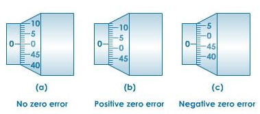
If the zero mark on the circular scale is below the base line of the main scale, the error is said to be positive. The number of circular scale division which coincides with the base line is multiplied with the least count of the screw gauge to get the positive zero error.
Negative Zero Error:If the zero mark on the circular scale is above the base line of the main scale, the error is said to be negative. Note the number of circular scale division coinciding with the base line. This number is subtracted from the total number of divisions on the circular scale and multiplied with the least count of the screw gauge. This gives the negative zero error.